sábado, 27 de noviembre de 2010

Energy Savings Using Series Drive in LED and Laser Diode Burn-in and Stress Systems

Overview

High volume LED (Light Emitting Diode) and Laser Diode applications often employ a parallel circuit configuration in which each device is powered individually using a simple linear regulator and a common low voltage bulk power source. For low power devices where current drive requirements are simple enough to be met with a resistor or monolithic regulator IC, this method is sufficient.

Figure 1: Series Mounted LEDs Undergoing Stress Screening

Considering higher power devices, the parallel drive scheme suffers from high losses in the regulators and other system components resulting in high costs. To reduce energy costs, devices can be arranged in a series circuit and driven with a single high compliance voltage regulator. This arrangement is much more efficient and leads to higher reliability. When properly implemented, series drive systems reduce electricity usage by over 60%. Series systems also allow for sophisticated drive and control, thus providing the ability to meet the complex specifications and test recipes for today and in the future. This white paper describes the benefits and energy savings when using the series method for high power LED and laser diode burn-in and stress test

Background

In a typical LED environmental stress screening or burn-in system, large numbers of LEDs are powered under room temperature or elevated operating temperature conditions (see Figure 1). The LEDs may be operated in one of many modes:

• Constant current mode such as that used in automobile headlamps;
• Pulsed mode meeting the needs of applications where flashing is important;
• Proprietary recipe where specific operating conditions must be validated.

The drive current is often elevated beyond the device's normal operating current. Current regulation is important as is thermal control. Usually these applications employ temperature chambers or thermal platforms to regulate the LED temperature. Heat removal is a big issue, especially with high power LEDs, as each device dissipates 1W or more. In large-scale operations, tens of kilowatts of power are consumed by hundreds of devices. Adding to this power dissipation is the power overhead, which consists of losses in the drive circuitry and the power needed for air conditioning and thermal control systems. This power overhead often exceeds the power driven to the devices themselves.

Parallel Drive System Requires High Current Supplies and Wiring

Using a parallel drive scheme, each LED is powered from a separate current regulator. At low currents a simple resistor can be used to regulate current. At higher powers a linear regulator is often used to provide a more accurate current. Each regulator is fed from a common bulk power source. Since the regulators are all in parallel, the total current draw from the bulk source is the sum of all the regulator currents. Figure 2 shows a typical design for a single 40 LED load board; note the current draw from the bulk power supply is 40 x If. In a typical LED burn-in system with ten 40 device load boards and with each device running at 1A current, the bulk power supply would need to supply 400A to the regulators. At 2A, 800A would be required.


Figure 2: Parallel LED Drive Requires High Current

Losses in Parallel Drive System

There are three main power losses in a parallel drive system: 1) losses in the linear current regulators, 2) losses in the cabling to the regulators, and 3) losses in the bulk power supply.

Regulator Losses Increase with Each Device Added to Parallel Drive System
Current regulators maintain a constant current by regulating a fixed input voltage to the output voltage that will result in the desired current through the LED. Linear regulators do this by dissipating some power as heat; switching regulators convert the power to a lower voltage. In both cases, the regulator requires a few volts of voltage differential between the input and output to operate properly. For the LM317 operating at 1A, this differential is about 4V. Thus the losses in the regulator are 4V x 1A = 4W. Since there is one regulator per LED, this loss is multiplied by the number of LEDs in the system. For a 400 LED system, this loss is 1600W.

Cable Losses May Exceed Hundreds of Watts
In the parallel system, the large number of regulators can be located near the LEDs, or they can be placed in external racks. Either way, cabling must connect the bulk power to the regulators. This cabling carries high currents and thus is subject to power loss that goes up with the square of the current. To some extent this can be combated with larger cable, but for high currents, cables become impractical and custom bus bars must be used. For a typical 400A system, these losses can easily be a few hundred watts.

Bulk Power Supply Losses Are Approximately 20%
The bulk power supply converts AC power to the DC voltage necessary to power the regulator banks. Low voltage power supplies in this class typically have losses of about 20% -- 2400W for the 1200A, 10V supply needed in this example.

Series Drive is Efficient

In a series drive system, the LEDs are arranged in a series circuit, and the entire circuit is powered from a single current regulator, usually a switching current regulator. In series drive, the same current
flows through each LED, and the current into the regulator is roughly equal to this current.
Since the LEDs are in series, the regulator supplies current at a voltage equal to n x Vf, where n is the number of LEDs in the series string. For a typical 40 LED circuit, like the one shown in Figure 3 with 3.75V average Vf, the regulator would need to supply current at 40 x 3.75V or 150V. In practice the regulator would be sized to handle the worstcase forward voltage of 40 x 4.5V or 180V.

In a series system, while the overall power delivered to the LEDs is the same as that in the parallel system, this power is delivered at a higher voltage and a lower current than in the parallel approach. This higher voltage distribution provides several benefits. These benefits are similar to those discovered by designers of the first electrical power distribution systems – systems that have uniformly evolved to high voltage, low current distribution.


Figure 3: Efficient Series LED Drive System
Minimal Losses Occur in Series Drive System

Losses in the series drive system are much lower than those of the parallel drive system.

Switching Current Regulator Operates with Conversion Efficiency of 90%
The switching current regulator used in the series drive system operates with a conversion efficiency of roughly 90%. For a 400 LED system operating at 1A with 3.75V average Vf LEDs, power losses in the current regulators are roughly 10% x 1A x 3.75V x 400 = 150W, which is roughly one tenth the losses of parallel regulators.

Cable Losses Are NegligibleIn the example 400 LED system with series drive, the bulk power supply needs to deliver 188V at 26A. Thus, there is no need for high current cabling, and cable losses are negligible.

High Voltage Bulk Power Supplies Operate at Twice the Efficiency of Low Voltage SuppliesHigher voltage bulk power supplies are much more efficient than equivalent low voltage supplies. To drive 400 LEDs in ten series strings, a 26A supply is required. This supply would have losses of roughly 10% or 495W – less than one fourth that of the equivalent low current supply.

Higher Voltage DUTs Can Be Supported
Since the regulator has high voltage capability, series drive can easily support newer high voltage DUT.

Series Drive – 62% Less Expensive To Operate

Annual and lifetime operating costs in US dollars for the two drive schemes are compared in the tables below. For these calculations, a $0.1 per kWh electricity cost was used. The energy required to remove heat was estimated.


As the tables show, the operating costs for series drive are 62% less than the costs of parallel drive when operating at 1A.

Other Considerations

In addition to electricity costs, there are other factors to consider when choosing between parallel and series drive.

LED Failures Must Be Handled
Series drive places multiple LEDs in the same circuit. When an LED in the series circuit fails, it can impact the others in the same circuit. There are two main LED failure modes that must be handled: short and open.

When an LED fails short, its Vf drops to near zero and the total string Vf is reduced. This sudden change can cause the current in the series circuit to spike up unless the regulator is designed to handle this. Vektrex's SpikeSafe current sources have built-in protection to prevent excess current. When LEDs fail in an open circuit condition, current flow stops in the circuit. For series systems this would mean that all of the LEDs in that circuit stopped operating--an undesirable result. To combat this, failed LEDs can be bypassed, either manually or with an automatic shunting circuit. For example, Vektrex's Shunt/Expander modules automatically sense an LED open failure and shunt current around the failed device.

Series Drive Simplifies System WiringParallel drive systems require fairly elaborate power distribution schemes. Fusing must be provided at various levels to ensure safety, and often there are many high current connection points in a system. This design tends to increase the number of connections in the system and decrease its reliability. Series drive has fewer, lower current connection points and is more reliable and easier to maintain.

Series Drive is More AccurateCurrent accuracy in the parallel drive system depends on the accuracy of the regulator IC and a power resistor. Typically these are in the range of 2-5%. For series drive, more expensive accurate components can be used. Typical accuracy for these components is in the range of 0.2-0.5%, roughly 10X better. It is also much easier to verify and calibrate a few series regulators rather than a few hundred parallel regulators.

Series Drive Enables More Sophisticated Current ControlParallel drive systems typically provide current adjustment by replacing fixed resistors. This scheme is time consuming and limited by gradations in standard resistor values. With series drive, a more sophisticated current regulator can be employed that allows for computer control of the current set point, current and voltage readback, and even pulsed current operation.

Summary

Series topology allows more efficient burn-in and stress systems to be constructed that use far less power. In addition, series drive simplifies system wiring and reduces cable losses. Together these savings dramatically reduce electricity consumption – a key consideration for system designers in today's energy conscious world. Series drive also enables more accurate, precise current control. Finally, it simplifies system design reducing operating and maintenance costs.

Wilmer J. Sánchez
V-19358601
Seccion 1
Fuente:http://www.vektrex.com/Support/kb/Vektrex%20AN112507%20Energy%20Savings%20Using%20Series%20Driver%20in%20LED%20and%20Laser%20Diode%20Burn-in%20and%20Stress%20Systems.pdf

Pulse testing 980-nm pump laser diodes in optical fiber amplifiers

Optical-fiber amplifiers help solve the bandwidth and attenuation problems of long-haul fiber links. Current research on erbium-doped fiber amplifiers which were first unveiled in 1987 promises improved reliability at lower cost, paving the way for economical broadband integrated services needed for the growing demand for communications services such as video-on-demand, home banking, teleconferencing, etc.

An essential accessory of the fiber amplifier is a pump source. This provides the energy for the amplifier itself which consists of several meters of glass-fiber whose core is doped with erbium. The erbium atoms are pumped through their absorption bands at 980 or 1480 nm,imparting energy to the incoming optical signal.

At the European Conference on Optical Communications, it was suggested there could be a trend away from the more established 1480 nm semiconductor laser pumps in favor of 980 nm ones because of higher efficiency and lower noise. Some types are also less sensitive to temperature,
eliminating the need for costly external cooling and show a reliability that could be as good or better than the 1480 nm lasers.

To gain better understanding of laser-diode pumps, Norwegian Telecom's Research Institute at Kjeller near Oslo fabricates and tests semiconductor lasers. Measurements are made under pulsed
conditions so that the lasers can be tested unmounted and without any heatsinking.

A low duty cycle assures negligible warming so that the device is neither damaged nor do its properties change. This way, individual diodes can be evaluated while they are still on the wafer.


Figure 1: Block diagram of a fiber amplifier
Although the diodes are driven by a dc in the target application, pulsed measurements are an accepted standard method of characterization. The measurements are performed using a pulse source, an oscilloscope to monitor the input current, and an optical power meter (see Figure 2).

The instruments are computer-contolled via GPIB. As also indicated in Figure 3, separate probes are used for supplying current and monitoring voltage of a particular laser on the bar.


Figure 2: Test setup
Figures 4 and 5 show the results of two measurements performed on the same laser diode, an uncoated 980 nm ridge waveguide laser with 5 um ridge width and 600 um cavity length. The first plot in Figure 4 shows the average optical power output for a range of peak pulse currents from about 20 to 90 mA in 1 mA steps. The second plot shows the voltage across the diode for each value of current. An attenuator is necessary for the small pulse amplitudes needed by diodes with very low threshold currents. Figure 5 shows the characteristics for higher currents. The laser diode is operated at currents up to 800 mA, an extremely high value for a narrow stripe laser, but a typical condition for a broadarea laser. In this case, the current is increased in 5 mA steps. The pulse generator allows the current to be programmed directly in terms of amps or mA.


Figure 3: Probe details

Figure 4: Laser diode I/P and I/V characteristics I< 90 mA
a) I/P characteristic (UP - LEFT)
b) I/V characteristic (UP - RIGTH)
Figure 5: Laser diode I/P and I/V characteristics I< 800 mA
a) I/P characteristic (DOWN . LEFT)
b) I/V characteristic (DOWN - ROGTH)

The above results are typical of measurements done regularly, in which 1 us pulses at a rate of 1 kHz
are often used. The form of the current pulse (Figure 6) through the diode - obtained by matching
the 50 ohm source resistance of the pulse generator to a load consisting of a 47 ohm resistor in series with the diode's forward resistance of about 3 ohm - is good enough for this application although it could probably be further improved by making the probe needles and the leads to the 47 ohm resistor shorter.

Another possibility would be to use the pulse generator's offset capability so that a small forward current exists between pulses. However, the offset current is, in contrast to the pulse current, created by a voltage source. This makes it difficult to control the exact base current through the diode.

Another reason for not using a dc bias is that at least 10 mA would be needed to obtain a resistance less than 10 ohm, and this would heat the diode.

In conclusion, the pulse technique for unmounted diodes gives consistent results with dc measurements made on heatsinked devices. This has the advantage that measurements do not have to be performed on expensive finished products. The Agilent 8114A pulse generator's clean current pulse through the laser diode is ne major contribution to this result. Another is the direct, accurate, programmability of the current.


Figure 6: Diode current


Wilmer J. Sánchez
V-19358601
Seccion 1
Fuente: http://cp.literature.agilent.com/litweb/pdf/5963-6988E.pdf

Geographic trends will shift in global laser-diode market

The worldwide laser-diode market can best be described as an oligopoly; an industry of many, controlled by a few. It consists of more than 25 companies worldwide that are competing for a pie, which Strategies Unlimited (Mountain View, CA) said in January 2005 is only about $225 million in size. These 25 companies are located throughout North America, Europe, and Asia (see figure). The controlling few are located in North America and Europe. They include (in alphabetical order) Coherent (Santa Clara, CA), Dilas Diodenlaser (Mainz, Germany), JDS Uniphase (JDSU; San Jose, CA), JenOptik Laser Diode (JOLD; Jena, Germany), and the Spectra-Physics Division of Newport (Mountain View, CA).


Major manufacturers in North America and Europe drive segmentation of the global
laser-diode market.

There seem to be several philosophical differences between manufacturers in North America and their counterparts located in Europe. These differences are in relation to supply chain, product development and technology, and global markets.

Supply chain

European suppliers—primarily Dilas, JOLD, and Thales Laser Diodes (Orsay, France)—tend to focus their supply chain on what might best be described as the back end of the process, or "packaging." European suppliers, historically, tend to view vertical integration as a noncritical factor in their supply chain. In this case, they outsource the epitaxial growth process, and view the unmounted bars (with mirror-facet coatings on them) as a "commodity" that they purchase, package, and then resell.

North American suppliers are, for the most part, "vertically integrated" and appreciate the advantages of controlling the entire supply chain, from epitaxial growth through processing and mirror-facet coating to packaging. Manufacturers in North America see epitaxial growth as a critical part of the supply chain because it allows better engineering and optimization of laser-diode structures, thus improving diode output in terms of quantum loss, efficiency, and performance. It also allows manufacturing customizability, with a host of volume opportunities demanding a variety of wavelengths, from 797 to 808 nm, 825, 880, 1470 nm, and beyond. In contrast, European suppliers tend to focus on just two wavelengths: 808 nm (used as a pump source for Nd:YAG, Nd:YVO4 lasers) and 940 nm (used as a pump source for Yb:YAG "thin disc" lasers).
Product development

In general, North American suppliers concentrate laser-diode product development on lower-power (less than 500-W class, 1.06-μm) industrial, commercial, and scientific diode-pumped solid-state (DPSS) lasers, and product development in Europe is dedicated to and driven by the needs of the automotive industry, which purchases multikilowatt (1- to 4-kW) DPSS lasers for automobile welding.

In North America, "ultrahigh" power and brightness is king. Manufacturers are focused on higher and higher continuous-wave (CW) output power from a 1-cm laser-diode bar rated from 80-, 100-, or even 150-W continuous wave. This was clearly seen at the Photonics West conference in January. The mean-time-between-failure (MTBF) rating demanded by end users of these industrial, commercial, and scientific DPSS lasers is on the order of 25,000 to 35,000 hours.

Europe has a different focus. In Europe, "ultralong reliability" is considered king of the industry, and thus directs European manufacturers' product development. European suppliers tend to work with, and focus development efforts on, increased lifetime, using 50- and 60-W CW 1-cm bars. Here, the demands of the automotive industry lead suppliers to develop MTBFs of at least 50,000 hours.

Driving forces in global market segments

In the 1990s, the European market matured into its current incarnation, due primarily to financial support from the German government. Dilas, JOLD, and Siemens began producing large quantities of pump laser diodes at 808 and 940 nm to supply the needs of the automotive industry, and in the U.S. the market was driven by lower-power DPSS lasers and the needs of the military, yet with only modest to no government input. In the U.S., the laser-diode market was first driven by the commercialization of the DPSS laser (795 and 808 nm) in the 1980s, then by the graphic-arts industry (825 nm) in the mid-1990s, and then by dermatology applications (laser-diode hair removal using 810-nm bars) in the late 1990s.

The philosophy in the U.S. was focused more on innovation and enabling new markets, with laser-diode companies competing to improve epitaxial structures, to develop and produce new wavelengths and packages, and to reliably manufacture higher-power laser diodes for an existing wavelength. The idea was that new technology would drive new applications and create new markets while exploiting existing ones. If the new laser-diode options were available, industry would find uses for them. And they did. Diodes were produced as pumps for DPSS lasers, which are, today, for all intents and purposes ubiquitous in the via-hole-drilling market, as well as in the DPSS marking and engraving industry. Other wavelengths were used by OEM applications for scientific, industrial materials processing, and therapeutic and diagnostic medical equipment.

The philosophy in Europe was to develop low-thermal-impedance packages that would become the foundation for ultrareliable laser-diode performance. The end goal was to produce reliable laser diodes for use in industrial automotive applications, such as a pump source for a multikilowatt DPSS laser or as a thermal source for direct diode welding and joining of aluminum and plastics.

Coming together

Interestingly, we anticipate that current trends in the market will actually flip. Europe will begin to focus on higher-power 1-cm bars, while still desiring a few select wavelengths and remaining dedicated to a few key industrial applications. In North America, the attention and focus will shift to laser-diode heatsink and packaging—striving for MTBFs greater than 80,000 hours across a wide range of wavelength offerings. Perhaps North America will still be seen as a leader in innovation, producing diodes in all colors of the spectrum, while continuing to increase the power output of these products.

Regardless of where Europe and North America choose to focus development, in the next five to ten years we can anticipate that the laser-diode market will continue to expand and will be dominated by new commercial applications—the consumer aesthetics market, the commercial laser-display market, and the automotive tail-light illumination market, among others. As technology advances in the laser-diode field, diodes will become ubiquitous. And, just as the nascent laser industry in the 1960s could not have predicted all of the varied market applications available today, we too can expect to be surprised by innumerable new laser-diode applications in the years to come.

Wilmer J. Sánchez
V-19358601
Sección 1
Fuente: http://www.nlight.net/nlight-files/file/articles/Geographic_Trends_June05_LFW.pdf

Monolithic Array of Laser Diodes Expand Laser Applications

Since the invention of the first optical laser in 1960 and the subsequent development of lowcost lasers for widespread applications by the 1980s, the potential of laser technology has sparked an intense pursuit of higher powered laser diodes. Applications as diverse as supermarket bar code scanners and photodynamic cancer therapies have spurred the search for better technology. Funding was not available to advance laser research, because it was too high risk and long term for investors. In 1991, SDL, Inc., in cooperation with Xerox Corporation and Stanford University, submitted a proposal to the Advanced Technology Program (ATP) to expand the laser applications base by developing a monolithic array of laser diodes that could be individually activated and emit light at predetermined wavelengths ranging from infrared to blue.

With the ATP award, the research team successfully developed high-performance, multibeam red laser diodes; two alternative methods for monolithic integrations of red, infrared, and blue emitters; and several valuable intermediary technologies. From these successes, the ATPfunded project built a strong U.S. technology base for multiple laser applications. Eighty-four inventions have been commercialized into numerous products. SDL (currently a part of JDS Uniphase) sells laser products for several markets, including high-speed color reprographics, optical data storage, displays, medical therapy, and telecommunications. Xerox used these technologies to enable a new generation of high-performance, high-speed printers and multifunction office product systems that are on the market today. These products enable companies to fulfill their printing requirements, such as one-to-one marketing and on-demand book printing, in minutes instead of days.

COMPOSITE PERFORMANCE SCORE

Laser Diodes Could Outshine Existing Technologies

By the 1990s, researchers understood the basics of optical lasers and were ready to exploit this technology. They imagined far-reaching applications for optical lasers, but many of the anticipated uses required that researchers move from infrared to blue lasers by developing shorter wavelength, higher powered laser diodes. SDL, Inc. and Xerox Corporation sought ATP funding to pursue single-mode laser diodes of previously unattained wavelengths and power levels.

Although the research team outlined several worthwhile intermediary technologies, they ultimately hoped to build a single semiconductor device with an array of lasers tuned to different frequencies, resulting in a monolithic array of diodes that would operate at predetermined wavelengths in blue, green, red, and infrared.

The plan involved technically aggressive milestones,and success would have a significant impact on several industries, such as colors, compact color projection displays, high-density optical storage systems, highresolution spectroscopes, medical devices, gas laser replacement markets, and medical therapy.

Proposal Highlights Impact to Multiple U.S. Markets

The companies' proposal to ATP highlighted the role of advanced laser technology in the growth of multiple industries over the next decade. For example, when this ATP-funded project commenced, the color printing and systems reprographics market promised lucrative opportunities for laser technology innovators. The U.S. xerographic marks-on-paper industry, valued at $48
billion in 1990, was expected to increase to $125 billion by 2000. Most of this increase would come from color printing systems and from replacing light-lens copiers with digital systems, if they were available. The reprographic industry needed the technology to develop compact printing engines capable of producing color graphics simply, quickly, and cost effectively.

At the time, existing high-speed printing systems were either limited in speed or needed to utilize complex multilaser optical systems. Limitations such as these also restricted the speed of color copier systems, which needed to print digitally in order to produce good print quality. SDL and Xerox proposed that monolithic multibeam lasers would enable print speeds to be increased, with a relatively small cost to the rest of the system. They further proposed that multiwavelength devices could enable new architectures in which single laser arrays would be able to address different photoreceptor layers.

The reprographic industry needed the technology
to develop compact printing engines. 

Thus, the SDL and Xerox team hoped to stimulate the expected growth of the color reprographic industry by providing the necessary technology for U.S. companies, including Xerox, Kodak, IBM, and 3M, to develop cutting-edge compact xerographic systems architecture. Other possible applications of the ATP-funded research included:

- Compact color projection displays that are better than cathode ray tube (CRT) or liquid crystal display (LCD) technology, because the brightness of a multiwavelength laser diode array greatly exceeds the brightness available for a CRT or an LCD.

- Optical data storage systems that can scan, store, and rapidly retrieve copious amounts ofdata from the small space of a compact disc. Because increased data density requires shorter laser wavelength emissions, the team's goal of developing laser diodes with wavelengths as low as 430 nm held high promise to increase data storage density by as much as 230 percent. This early effort in bluelaser development was a precursor to later efforts using cyan lasers for DVDs.

- Retail bar code scanners would be more reliable and cost significantly less if they were based on a 630-nm laser diode instead of the existing gas laser technology.

- Photodynamic therapy (PDT) was a laserpowered alternative to chemotherapy that uses laser light in combination with photoactive drugs called photosensitizers that target and destroy diseased cells while limiting damage to surrounding healthy tissue.

- Noninvasive glucose monitoring would allow more than 20 million diabetics in the United States alone to manage their blood sugar levels with laser technology rather than using needles.

- Aggressive Technology Goals Target Development of High-Power Lasers

Through its ATP-supported research and development (R&D) efforts, the research team wanted to combine the features of high-power, single-mode output, widerange wavelength accessibility, and close-aperture spacing in a compact and manufacturable laser diode. The researchers hoped to develop several contributing technologies, including the following:

- High-power visible laser diodes operating at greater than 100 mW with continuous wavelengths  between 630 nm and 680 nm

- High-power, single-mode laser diodes operating between 700 nm and 780 nm

- Monolithic integration of multiwavelength laser diodes operating between 630 nm and 1.1 mm

- High-power, frequency-doubled laser diodes with wavelengths between 430 nm and 550 nm in hybrid format

- Epitaxial format (a single crystal layer growth of ferroelectric materials)

The research team expected to expand the U.S. knowledge base in key technologies, including visible
laser growth capabilities; high-power, single-mode device design; epitaxial growth of ferroelectric materials; and frequency-doubling techniques

ATP Funding Needed to Jump-Start Research

Before the ATP-funded project, laser technology presented a wide field of opportunity that was simultaneously enticing and intimidating to companies in various industries. The sheer magnitude of possibilities for laser technology made it difficult for any one company to take on the expense or risk of generic research. Venture capital firms shunned investment in laser technology for the same reason: initial research was high risk, broad based, and unlikely to yield a quick turnaround from technology to profitable products. Other sources of government funding, such as the Defense Advanced Research Projects Agency (DARPA), required that laser research produce technology for a specific application, such as missile defense or data storage.

ATP provided the jump-start by supporting the productive partnership between Xerox, a company
interested in lasers specifically for xerographic applications; SDL, a company aiming to supply laser
products to multiple industries; and Stanford University, which provided research support in modeling the frequency-doubling waveguides for the short wavelength devices. The project established broad laser capabilities and stimulated subsequent investment in application-specific research.
For example, SDL and Xerox joined Hewlett-Packard and others in an $8 million research program co-funded by DARPA to develop blue semiconductor lasers and light-emitting diodes (LEDs). Because of this ATPfunded project's success, Xerox's Palo Alto Research Center received approximately $8 million in internal R&D funds over four years for blue-laser-diode research to advance its xerographic products. SDL later channeled its knowledge into the telecommunications
industry, where multiple lasers traveling on one fiberoptic cable allow faster Internet communication.

Technical Successes Lead to Commercial Impact

The R&D work of scientists from SDL, Xerox, and Stanford became a prolific source of new laser technologies. Donald Scifres, president of SDL at the time of the project, pointed out that without ATP, development of these technologies would have taken much longer, in an industry where time is critical. The ATP research team achieved several breakthroughs, including demonstrations of red lasers with powers up to 120 mW in single mode, lasing in the previously unattained 700- to 755-nm range, and green and blue lasers by frequency doubling. By the end of the project, SDL offered some of the lowest threshold laser devices available. Because low-threshold lasers produce less heat, which translates directly to higher data densities, SDL used these devices to produce competitive printingand data storage laser products. After it became clear that the se devices were ideal for reprographic and printing applications, researchers also developed two alternative methods for monolithically integrated red, infrared, and blue emitters.

The transformation of the laser industry from gas tube lasers to semiconductor optoelectronic integrated circuits (OEICs) created a huge global market. "We were the first company in the world to successfully commercialize the integration of multiple lasers on a single OEIC device," said Scifres. This resulted from developing high-performance, multibeam red and infrared lasers by the end of the project in 1997. These multibeam lasers enabled a new generation of highperformance printers and multifunction office product systems later introduced by Xerox. Today, these machines continue to generate a large percentage of Xerox's total revenue and to create economic spillover for companies whose short-run office needs were met previously by lithographic printers that required several
days to fill orders. These companies can now fulfill their printing requirements in just minutes, thereby increasing business efficiency.

The R&D work of scientists from SDL, Xerox,
and Stanford became a prolific source of new
laser technologies

Digital printing capabilities that improved as a result of the ATP-funded project also enabled Xerox to tap the emerging "print-on-demand" market, which boasted a retail value of $21 billion in 2000. Xerox now sells printon-demand machines that can print, cover, and glue a 300-page book in just over a minute, enabling rapid production for internal corporate and government publications departments and commercial print shops. These machines allow retailers to produce a customized sales brochure for each customer's model and color specifications, called one-to-one marketing.

The research team also completed significant work with gallium nitride (GaN)-based blue laser diodes, an area that began as a small focus of the project but became an increasingly attractive prospect during the research. After a breakthrough demonstration of long-lived blue LEDs in the GaN materials family by Nichia Chemical of Japan, SDL and Xerox decided to concentrate greater effort on blue laser diodes. They made this decision because of the diodes' appealing lower cost, higher efficiency, and smaller size compared with small gas lasers or frequency-doubled, diode-pumped solid-state lasers that require high power to double the frequency of red light. By shifting their focus to blue laser diodes, the researchers established epitaxial growth capability, fabricated high-quality LEDs, and demonstrated pulsed blue laser diodes. The main application for blue laser diodes was in highdensity optical storage. Since the end of the project, Xerox has continued to develop these devices, although to date they have not been introduced in Xerox products. SDL's smaller applications that take advantage of blue diodes include color printing (using blue diodes to expose commercial printing plates), biotechnology (DNA sequencing and cytometry), and measurement and inspection.

The transformation of the laser industry from gas
tube lasers to semiconductor optoelectronic
integrated circuits (OEICs) created a
huge global market.

PDT technology has benefited significantly from the project's 635-nm single-mode laser diode. In the United States, PDT is currently used for treating cancer and a wide variety of other medical disorders. The combination of fiber delivery and the efficient laser diode source allow production of hand-held, portable machines that are highly reliable and moderately priced. Moreover, they consume less power and provide flexible energy delivery to the target. Previous PDT systems utilizing this wavelength relied on gas lasers and were unreliable, large, and expensive. The new laser flexibility allowed the development of new medications for treatment, with fewer side effects. SDL won the "Photonics Circle of Excellence Award" in 1999 for this work. In early 2000, the Food and Drug
Administration approved the use of PDT for treating wet macular degeneration, a retina disorder (see illustration below).

The development of these technologies has enabled SDL to deliver laser products for applications ranging from optical storage to medical therapy, a laser diode for printing and data storage, and fiber-coupled laser bars for medical systems and displays. SDL revenue leveraged from the 84 technologies developed during the course of the ATP-funded project, particularly from red laser diode  technologies, totaled $18.25 million from 1993 to 1997. The company grew from 200 employees
in 1992 to 1,700 in 2000, prior to the merger with JDS Uniphase.

Broad Laser Capabilities and Bright Futures for SDL and Xerox

By 1998, SDL had attracted top researchers and had established broad capabilities in laser technology, in part because of the accomplishments of the ATPfunded project. With a solid track record in developing and commercializing innovative products, SDL felt confident in enlarging its strategic focus into the dynamic telecommunications industry, applying some of the laser technologies developed in this project directly to the new focus area. After making successful strides
in this direction, SDL drew the attention of telecommunications leader JDS Uniphase. Evolving
technology and fierce global competition were leading to consolidation in the high-tech industry, and, in 2000, JDS Uniphase acquired SDL for $41 billion.

Today, JDS Uniphase focuses mainly on laser technology for fiber-optic telecommunications, using wavelengths of light from multiple lasers to travel simultaneously on one fiber-optic cable; this technology helps to reduce congestion on the Internet. A small division of the company remains committed to discovering applications for viable blue laser diodes. Some SDL components, such as the Laser Diode Driver, are being manufactured by third parties.

Xerox's customers continue to benefit from the ATPfunded technology, because the project's multibeam red lasers now enhance the majority of Xerox's xerographic systems. Moreover, the company is continuing its blue laser diode R&D to further enhance its products.

Conclusion

During this ATP-funded project, the SDL and Xerox research team, in conjunction with Stanford University, developed high-performance, multibeam red laser diodes; two alternative methods for monolithic integrations of red, infrared, and blue emitters; and several valuable intermediary technologies. These successes helped to build a strong U.S. technology base for multiple laser diode applications, allowed Xerox to manufacture best-in-class xerographic systems, and propelled SDL to the forefront of laser technology for the telecommunications industry. This ATP-funded project has also resulted in the filing of 29 patents of which 27 were granted.

Wilmer J. Sánchez
V-19358601
Seccion 1

High Density Pulsed Laser

1. INTRODUCTION
Laser diode arrays are used in a variety of defense and aerospace applications. Two of the most common uses are illumination and solid-state laser (SSL) pumping, in which the radiation from the diode lasers is used to excite the laser crystal in order to generate light. The SSLs can then be used in a number of configurations and applications, including range finding and target designation.

In many SSL applications it is common to operate the laser diode arrays in pulsed, or quasi-continuous wave (QCW) mode. In this regime the diodes are electrically pumped with a pulse width that is commonly on the order of the upper state lifetime of the laser gain medium. For example, Nd:YAG lasers are typically pumped with pulse widths on the order of 200 us. This pumping scenario leads to efficient laser designs since most of the pump light that is absorbed by the laser crystal can be extracted from the system. The repetition rate of the diode pumps is also defined by the application. Many range finding applications operate in the 10-30 Hz range, and many direct diode illuminations operate at around 60 Hz to match the frame rate on commercial off the shelf (COTS) camera systems. QCW diode pumping holds several advantages over CW diode pumping in SSL systems. First, QCW pumping creates a lower average thermal load in the laser gain medium.

This simplifies the cooling of the system and also enables higher beam quality lasers due to the reduced thermal lensing effects. Second, QCW pumping allows the diodes to be operated at higher peak power than is possible with CW pumping. This leads to SSL systems with higher peak powers.
Northrop Grumman Cutting Edge Optronics (NGCEO) has been manufacturing QCW laser diode arrays for over a decade in a variety of configurations. A schematic of the standard manufacturing process for a QCW diode array is shown in Figure 1. In the first step, a diode bar is soldered to a heatsink. A heatsink with a coefficient of thermal expansion (CTE) near that of the bar (~ 6 ppm/K in the case of GaAs) is used. This allows for the use of hard solders such as eutectic AuSn, which minimizes solder creep and promotes a high degree of reliability. The subassembly created when a bar is soldered to a heatsink is known as a Mounted Bar Assembly (MBA).

In the next step of the standard manufacturing process, a number of MBAs are soldered together and attached to a ceramic backplane and electrical contacts to create a diode array. The electrical contacts also serve as large heatsinks on the end of the array. The bar-to-bar spacing, or pitch, is defined primarily by the thickness of the heatsink and whether there is any space between the MBAs. Pitch values ranging from 350 >m to 2 mm are common in the industry today. The number of bars in the array is determined by the customer specification and is directly related to the desired output power of the device. The array can be subsequently attached to either a water- or conductively-cooled heatsink.

Figure 1. Assembly process for standard pulsed diode arrays at NGCEO.
In defense-related applications, it is often advantageous for the laser diode arrays to have a very high output power density. High diode output power densities enable the use of smaller laser crystals and also have a direct impact on the size, weight, and cooling requirements of the resulting laser system. For arrays built using the process in Figure 1 using COTS diode bars rated at 200-300 W/bar, the resulting power density is 5-8 kW/cm2.

There are several ways to increase the optical power density of a laser diode array. The first is to increase the output power of each of the diode bars that comprises the array. Additionally, optical methods (e.g. interleaving, beam combining) can be used to generate arrays with higher power densities.

NGCEO has created a new array design that eliminates the heatsinks from between the diode bars and drastically reduces the bar-to-bar pitch. This design is called the High Density Stack (HDS). A schematic of this manufacturing process is shown in Figure 2. In this process, a stack of laser diode bars is joined together using AuSn solder. This stack is then attached to a ceramic backplane and electrical contacts in a subsequent soldering step. The resulting array has a bar-to-bar pitch of ~ 150 >m. This pitch is approximately 43% of the smallest industry-standard pitch that can be obtained from the method shown in Figure 1, above. This leads to optical power densities that are approximately 2.3 times higher than can be obtained using standard manufacturing methods.

Figure 2. Assembly process for High Density Stack arrays at NGCEO.
Figure 3 contains a graph of diode array power densities (in kW/cm2) as a function of the power per bar and the bar-tobar pitch. The data illustrates that by utilizing the HDS architecture, significant increases in power densities can be achieved. At a nominal output power of 150 W/bar, the 10-bar HDS array has a power density ~ 2.7 times greater than that obtained from a standard array with 400 >m pitch. In fact, a 10-bar HDS array operating at 150 W/bar has the exact same power density as a 10-bar, 400 >m pitch array operating at 400 W/bar. This gives a system designer greater flexibility when selecting diode arrays for his/her application. Bars with lower peak power can be selected in order to operate further from the catastrophic optical damage (COD) limit, or to make use of lower-current diode drivers.
 
Figure 3. Power density as a function of power/bar for arrays with different pitch values.
While the increased optical power density of the High Density Stack arrays is a desirable feature, the array design possesses an intrinsic limitation. The absence of the interposing heatsinks means that all of the heat generated by the interior bars must travel through the adjacent bars to the electrical contacts. As a result, the allowable operating envelope of the HDS arrays is smaller than the perating envelope of arrays built using standard manufacturing processes. One goal of this work is to define the operating envelope in which the HDS arrays can be used reliably.

2. EXPERIMENTAL DATA

The bars used for this experiment were designed and fabricated by NGCEO specifically for high power QCW operation. The bars are 1cm in width and have a 1mm cavity length with a fill factor of approximately 83%, and the output facets are passivated to prevent oxidation. These bars are nominally rated as 200W bars and achieve that power level at 175- 180 A. In a standard package, this bar has been shown to have > 50% electrical-to-optical efficiency at temperatures H 70 oC and has also been shown to withstand significant thermal shocks [1]. In addition, this bar/package combination has been shown to have device lifetimes in excess of 13 billion shots [2]. This proven bar is therefore an excellent candidate for use in the HDS arrays.

In order to determine the operating envelope of the HDS arrays, 5-, 10-, and 20-bar arrays were fabricated using the process highlighted in Figure 2, above. All devices were fabricated from the same bar lot in order to allow for direct comparison of the data sets. In the case of the 5- and 10-bar stacks, the stack was built using a single soldering step. In the case of the 20-bar stack, two 10-bar stacks were joined together in a subsequent soldering step.

A picture of a 5-bar HDS array is shown in Figure 4, directly adjacent to a standard array with 400 >m pitch. In this case additional CuW heatsinks were added to the outside of the 5-bar stack so that the entire assembly could maintain the same form factor as the standard assembly for ease of testing. However it is clear that the emission area is significantly smaller for the HDS array. The total emission area of the standard array is 1cm x 1.6mm, while the emission area for the HDS array is 1cm x 0.6mm. For the case of two five-bar arrays operating at the same output power, the HDS array therefore has a 2.6 times greater power density.
Figure 4. Photograph of two 5-bar stacks placed end-to-end. The High Density Stack is on the op and a standard array with 400 3m pitch is on the bottom.
The difference in power density can also be illustrated by looking at near field images. Near field images were obtained from the 5-bar HDS array and a 5-bar array with 400 um pitch and are shown in Figure 5. This clearly shows the advantage of the increased power density associated with the HDS array.


Figure 5. Comparison of example near-field images from a High Density Stack (left) and a standard array with 400 3m pitch (right). Each array contains five bars.
Near field images for all three stacks are shown in Figure 6. In the 5- and 10-bar stacks, each of the emitters in all of the bars is lasing. In the 20-bar stack, however, three bars contained multiple emitters with little or no emission.This results in a lower peak power per bar for the 20-bar stack even at low average currents, as will be shown below.


Figure 6. Near field images from 5-10-, and 20-bar High Density Stack arrays.
Power vs. current data was obtained for a 5-bar HDS array and compared to a 5-bar array built using standard manufacturing methods with bars located on a 400 um pitch. The data was obtained at a repetition rate of 20 Hz and a pulse width of 150 us and is shown in Figure 7. There is no discernable difference in output power between the two arrays over the range of test currents. Since 20 Hz, 150 us is a very common drive condition for pumping Nd:YAG in SSL range finders, this test result validates the use of the HDS arrays in this regime.

Figure 7. Power vs. current for a High Density Stack and a standard array. Each array contains five bars. This
test was conducted at 20 Hz, 150 3s.
Additional testing was conducted to determine the effect of increasing the pulse width on the output power of the HDS arrays. Peak power/bar as a function of pulse width is presented in Figure 8. For this test, the repetition rate and drive current were held constant at 20 Hz, 200 A.For all three arrays the peak power decreases as the pulse width is increased due to heating throughout the device.

The 20-bar stack produced 94% of the power/bar as the 5- and 10-bar stacks at a pulse width of 150 us. At first glance one would suspect that this was due to the presence of several missing emitters, as seen in Figure 6. However, only ~ 2% of the emitters are emitting significantly less power according to the near field image. Therefore one can conclude that the decrease in output power is likely due to some other factor, most likely excessive heating in the device. At a pulse width of 450 >s, the 20-bar array experienced thermal runaway and no meaningful data could be collected.


Figure 8. Power/bar as a function of drive pulse width for 5-, 10-, and 20-bar High Density Stacks. All data
obtained at 20 Hz, 200 A.
The relationship between the junction temperature of the device and the output wavelength is well understood, and scales at a ratio of ~ 0.25 nm/K for this material set. Because of this, measuring the output wavelength of the High Density Stack arrays provides a measure of the junction temperature. The center wavelength value for each array was collected during the testing of Figure 8, and is plotted in Figure 9. At low pulse widths (~ 75 us), all three arrays have similar center wavelengths. The 5- and 10-bar arrays have the same center wavelength (to within the resolution of the measurement), and the 20-bar array is higher by ~ 1 nm.

The performance of the arrays begins to diverge as the pulse width (and therefore the average heat load) is increased. The 5- and 10-bar arrays have similar output wavelengths over the range of pulse widths in the test. At a pulse width of 450 us, the wavelength of the 10-bar array is only ~ 2 nm higher than the 5-bar array. This corresponds to an average temperature increase of ~ 8K over the entire array. However, the center wavelength of the 20-bar array is a rapidly increasing function of pulse width.

It should be noted that at drive conditions common to Nd:YAG pumping for range finding applications, all three arrays were operating at junction temperatures less than what are typically experienced by CW arrays that are common in the industry today. Therefore at 20 Hz, 150 >s, and 200 A (~ 210 W/bar), all of the arrays are capable of high reliability operation.


Figure 9. Center wavelength as a function of drive pulse width for 5-, 10-, and 20-bar High Density Stacks. All
data obtained at 20 Hz, 200 A.
3. FUTURE DIRECTION

The data presented above was based on NGCEO's 200W laser diode bar. Recent advancements in epitaxial design have led to a bar that is capable of reliable operation at 300W (at approximately 300A). A comparison of the P-I curves for the two epi structures is shown in Figure 10.

Figure 10. Power vs. current for NGCEO's new epitaxial design, compared to the standard epitaxial design used
for the High Density Stack arrays in this work.
The future direction of this project will be focused on the testing and evaluation of the new epitaxial structure in the HDS architecture. With reliable per-bar power levels in excess of 300 W, the HDS arrays will be capable of producing power densities approaching 25 kW/cm2.

4. CONCLUSIONS

Northrop Grumman Cutting Edge Optronics has demonstrated a new laser diode array design capable of power densities of ~ 15 kW/cm2 when operating at 200 W/bar. This array design, called the High Density Stack, enables high power densities by packaging the diode bars with a bar-to-bar pitch of ~ 150 >m. NGCEO has collected data for 5-, 10-, and 20-bar arrays in the operating regime common to many Nd:YAG pumping schemes. The data collected from these experiments verifies that the arrays operate at junction temperatures that are suitable for long lifetimes.

Wilmer J. Sánchez
V- 19359601
Sección 1
Fuente:http://www.as.northropgrumman.com/businessventures/ceolaser/technical_papers/assets/AppNote15_High_Density_Stacks.pdf

Utilización del láser diodo en la vía aérea pediátrica

INTRODUCCIÓN

En los pacientes pediátricos las anomalías de la vía aérea representan un reto terapéutico debido a sus diferencias anatómicas, su acceso limitado y la potencial morbilidad derivada del edema producido por la manipulación. Es por eso que el tratamiento con láser de las lesiones de la vía aérea es una
opción terapéutica muy atractiva por sus buenos resultados funcionales con una limitada reacción inflamatoria tras la fotocoagulación y su relativa facilidad de ejecución técnica en unas estructuras de dimensiones reducidas(1). Entre los numerosos tipos de láser utilizados en cirugía, el de dióxido de carbono (CO2) ha sido el láser de elección durante muchos años, pero la reciente aparición del láser diodo representa una nueva opción emergente. Basado en la aplicación de los semiconductores es un instrumento capaz de transmitir a los tejidos una energía variable entre 15 y 60 Wcon una longitud de onda entre 800 y 940 nm. Esta longitud de onda es absorbida selectivamente por cromóforos tisulares (melanina, hemoglobina) lo que hace muy útil en la vaporización, corte y coagulación de tejidos con una mínima necrosis(2). Generado mediante un sistema electrónico y controlado por software,
su principal ventaja es su transmisión por un sistema de fibras ópticas flexibles y su aplicación por contacto a los tejidos, que permite mayor operatividad y un máximo control. En el mercado existen aparatos de menos de 15 kg de peso, lo que lo hace además fácilmente transportable (Fig. 1).
En este trabajo presentamos nuestra experiencia preliminar en el tratamiento quirúrgico endoscópico de las anomalías de la vía aérea en niños utilizando láser diodo.

MATERIALY METODOS
Veintidós pacientes (once niños y once niñas) en edades comprendidas entre el mes y los 13  años edad media de 1 año y once meses), fueron tratados endoscópicamente con láser diodo desde el año 1999 hasta el 2006. Diecinueve de ellos fueron tratados en nuestro centro primariamente y otros
3 enfermos fueron derivados a nuestro centro tras un tratamiento con láser previo. Todos los rocedimientos fueron realizados con láser diodo de contacto aplicado a través del canal de trabajo de un fibrobroncoscopio mediante fibras ópticas de 400 o 600 μm con un haz apuntador de diodo láser visible.
Figura 1. Aparato portátil de láser diodo y fibra óptica para su aplicación
Para ello utilizamos el láser Diomed 15 plus® que emite a una longitud de onda de 820 nm + 20 nm en pulsos de 1 seg a una energía entre 10 y 15 Wsegún los casos. El fibrobroncoscopio se introduce a través de la mascarilla laríngea. Durante la aplicación se utiliza una fuente de aire medicinal para el fibrobroncoscopio y una concentración de oxígeno al 21% para la ascarilla, con el fin de evitar la generación de fuego en la vía aérea. Las indicaciones que nos han llevado a realizar un tratamiento endoscópico con láser de la lesión fueron enormemente variadas: laringomalacia grave y lesiones de aritenoides en cinco casos, angiomas y linfangiomas con 3 casos cada uno,
3 pacientes presentaban quistes saculares u otras lesiones mucosas (membranas), se trataron 3 casos de granulomas intraluminales, 4 de lesiones cicatriciales (3 estenosis subglóticas y una estenosis traqueal) y 1 caso por parálisis en adducción de las cuerdas vocales. Hemos analizado las variables: tiempo de intubación, tiempo de estancia en UCIP, número de procedimientos, complicaciones y los resultados a medio plazo, analizados según una escala clínica de 1-4. Siendo 4: resultado excelente (el paciente no presenta estridor ni dificultad respiratoria); 3: resultado bueno (el paciente presenta un mínimo estridor con el ejercicio, pero sin dificultad respiratoria); 2: resultado regular (el paciente presenta estridor en reposo y dificultad respiratoria con el ejercicio); y 1: resultado malo (el paciente presenta estridor y dificultad respiratoria en reposo o necesidad de reintervención quirúrgica).
RESULTADOS

Ningún paciente ha presentado complicaciones relacionadas con la aplicación del láser diodo endoscópico. La media del número de procedimientos realizados en cada paciente ha sido 1,4 (rango entre 1 y 3 procedimientos). El tiempo medio de intubación tras el tratamiento ha sido de 2,8 días (rango entre 4 horas y 13 días). La media de tiempo de estancia en UVI tras la aplicación del tratamiento ha sido de 4,6 días (1-8 días). Los mejores resultados se han conseguido en los pacientes
con quistes saculares o lesiones mucosas, excelente en los 3 casos y en los 3 pacientes con un granuloma endotraqueal también con resultado funcional excelente. En los 5 pacientes con lesiones de aritenoides hemos obtenido un resultado funcional excelente tras una media de 1,4 procedimientos (rango de 1 a 3). Los enfermos con lesiones vasculares han presentado un resultado variable. De los pacientes con angioma subglótico 2 han requerido una reintervención por presentar estenosis subglótica residual y otro ha precisado corticoterapia a altas dosis tras el láser. De los enfermos con linfangioma subglótico, uno se ha resuelto tras 3 procedimientos endoscópicos y 2 han precisado una resección quirúrgica posterior por recidiva.
La paciente con parálisis de cuerdas vocales ha presentado un resultado excelente tras 2 rodecimientos. De los 4 pacientes con lesiones cicatriciales, las 3 estenosis subglóticas han precisado una intervención quirúrgica tras el tratamiento con láser. El primero de ellos es una paciente
derivada a nuestro hospital por mala evolución con reestenosis tras la aplicación de laserterapia por estenosis subglótica en otro centro. Se realiza resección cricotraqueal posterior tras comprobar una estenosis suglótica grado IV a la exploración, con buenos resultados. El segundo presentaba una membrana subglótica grado III en la que se intentó resección con láser. Tres meses después requiere una laringotraqueoplastia parcial anterior por presentar una estenosis residual circular grado II y persistencia del estridor. El tercero es un paciente con una patología bronco-pulmonar compleja de base, en el que la aplicación del láser reduce una estenosis subglótica del 75 al 50%, persistiendo el paciente con clínica clínica.
La estenosis traqueal grado II, muy segmentaria, se ha resuelto con un único procedimiento, la paciente presenta un mínimo estridor sin repercusión funcional. No se observaron complicaciones intra ni postoperatorias en ninguno de los pacientes tratados. En la figura 2 se muestra una gráfica en la que se representan los resultados obtenidos. Las lesiones saculares, mucosas, granulomas y anomalías de los aritenoides se resolvieron mediante la aplicación exclusiva de láser (el 78,6% con un
único procedimiento). En otras situaciones, como las anomalías vasculares (angiomas y linfangiomas) y estenosis subglóticas, hemos precisado de otros tratamientos (87,5% quirúrgico y 12,5% médico) para su resolución.

Figura 3. Momento de aplicación del láser diodo en un paciente con
                                   parálisis de cuerdas vocales


DISCUSIÓN

En los pacientes pediátricos las anomalías de la vía aérea representa un reto terapéutico debido a sus diferencias anatómicas, con menores diámetros y tejido más laxo, su acceso limitado y la potencial morbilidad derivada del edema producido por la manipulación. Dentro de las diferentes opciones de tratamiento el láser se ha erigido como una herramienta muy útil que se lleva utilizando de forma rutinaria desde hace más de 20 años(1). Las primeras series recogidas se refieren a su aplicación para el tratamiento de papilomas en adultos. Con el tiempo se han ampliado sus indicaciones a otras patologías y a medida que aparecía el material necesario se ha ido extendido su uso a los niños. Sus buenos resultados funcionales con una limitada reacción inflamatoria tras la fotocoagulación y su facilidad de ejecución técnica en unas estructuras de dimensiones reducidas como ocurre en la vía aérea pediátrica lo convierten en un arma ideal con múltiples aplicaciones (Fig. 3). El láser gracias a sus propiedades entra a formar parte del armamento terapéutico del cirujano pediatra. Según la pato-
logía puede resultar altamente eficaz como terapia única, mientras que en otras situaciones puede ser utilizado como adyuvante o complemento. Es necesario siempre hacer un enfoque individualizado y una adecuada selección de pacientes para unos resultados óptimos.
Desde su primera indicación en los papilomas, su uso se ha ido extendiendo hasta ser aplicado en diversas patologías y hoy en día son numerosas las lesiones de la vía aérea que pueden ser tratadas con láser. En la papilomatosis el objetivo es la resección del papiloma con el mínimo trauma. Es una
de sus principales indicaciones, aunque su resección es siempre paliativa, dado el origen infeccioso de la enfermedad(2). En los quistes saculares es necesaria su escisión o marsupialización por la  osibilidad de obstrucción de la vía aérea. Su manejo con láser está bien establecido con buenos resultados(3). De acuerdo con la literatura en nuestra serie los 3 casos se resolvieron satisfactoriamente con un solo procedimiento, con un resultado funcional excelente. En laringomalacias moderadas-severas en las que están indicadas algún tipo de actuación, la supraglotoplastia con escisión de tejido redundante supraglótico mediante láser ofrece buenos resultados(4). La estenosis supraglótica es la complicación más grave de esta técnica. Para prevenirla es importante dejar intacta la mucosa de la comisura posterior. En nuestra serie hemos realizado epiglotoplastias en 5 pacientes obteniendo un resultado funcional excelente tras una media de 1,4 procedimientos. Otra se las indicaciones más establecidas del láser en la vía aérea es la vaporización de granulomas(5). Los resultados de nuestros pacientes han sido muy satisfactorios con resultados funcionales excelentes sin estenosis cicatricial posterior. En la parálisis de cuerdas vocales en adducción permite realizar una aritenoidectomía y/o cordectomía posterior, ofreciendo resultados que garanticen una vía aérea suficiente con una calidad de voz aceptable(6,7). Se recomienda respetar la integridad de las comisuras anterior y posterior, para reducir el riesgo de cicatrices y realizar la resección de la mitad o dos tercios posteriores por la posible hipertrofia compensadora(8).
Nuestra paciente ha necesitado dos aplicaciones de láser diodo tras las que no presenta disnea y no ha empeorado la disfonía respecto al preoperatorio. Las estenosis subglóticas grado I y II leves pueden manejarse mediante técnicas endoscópicas(5,9). Se describen entre los factores predisponentes al fracaso de la aplicación del láser la longitud de la lesión (mayores de 1 cm), lesiones circunferenciales, la falta de soporte cartilaginoso subyacente o la afectación de la comisura posterior(10,11). La complicación es la exposición del pericondrio o del cartílago, con la consecuente pericondritis o condritis que puede llevar a la formación de tejido de cicatrización y reestenosis. En nuestra opinión
el tratamiento estándar para la estenosis subglótica es la cirugía, y el láser debe quedar reservado para casos muy seleccionados. Algunos autores consideran que el Nd-YAG, el KTP y el diodo pueden tener una mayor tasa de reestenosis respecto al láser CO2. Por último, gracias a la absorción del láser por la hemoglobina se usa en lesiones vasculares. Desde que se utilizó por primera vez el láser CO2 para el tratamiento de angiomas subglóticos hace casi 30 años, el manejo endoscópico forma parte del arsenal terapéutico, junto con la corticoterapia y la cirugía abierta. Las lesiones pequeñas, unilaterales y únicas son que ofrecen mejores resultados a la aplicación del láser, mientras que en los angiomas circunferenciales o bilaterales debe considerarse la indicación quirúrgica(10,12). En otros pacientes puede utilizarse de forma complementaria junto con los corticoides para reducir el tamaño del angioma, mientras estos hacen efecto o en combinación con técnicas quirúrgicas. En nuestra serie uno de los casos se trató complementariamente con corticoides y los otros dos casos requirieron una cirugía posterior, al producir la cicatrización del procedimiento una estenosis subglótica cicatricial.
El tratamiento del linfangioma mediante la tecnología láser (Nd:YAG, CO2 láser o láser diodo) tiene la ventaja de menor dolor postoperatorio y menor hemorragia(13). Al reducir el tamaño del tumor contribuye a resolver la obstrucción y es interesante su uso como tratamiento sintomático en caso
de obstrucciones con afectación intrínseca de la vía aérea(13,14). Debe complementarse con otras técnicas (terapia esclerosante y resección quirúrgica). Cada una de estas anomalías puede abordarse con distintas técnicas quirúrgicas. El láser ofrece frente a la cirugía abierta convencional un manejo endoscópico con menor invasividad y una más rápida recuperación.De los distintos tipos de láser el más ampliamente utilizado y descrito en la literatura para el tratamiento de lesiones en la vía aérea es el láser de CO2. En comparación con el láser Nd:YAG, sin aplicación por su alta capacidad de penetración (hasta 4 mm), el láser de dióxido de carbono presenta menor penetración (de 30 μm) con un mínimo efecto termal, lo que lo convierte en el láser ideal para su uso en la vía aérea pediátrica(
9). Su longitud de onda de 10,6 μm se absorbe de forma preferente por el agua, y actúa en la parte invisible del espectro (por lo que ha de ser utilizado junto con un haz lumínico).
Su capacidad hemostática está reducida a la microcirculación (vasos de un calibre menor a 0,5 mm).
La principal desventaja de este tipo de láser es que no puede ser transmitido a través de fibras y ha de manejarse por medio de un brazo articulado, lo que hace necesario la utilización de un broncoscopio rígido, dificultando su uso en lesiones distales o de lóbulos superiores y en niños de menos de 7
kg de peso(15). Otro de los láseres utilizados es el KPT que emite a una longitud de onda de 532 μm (visible) siendo absorbido por cromóforos con una capacidad de penetración de 0,9 mm. Tiene
la ventaja de transmitirse a través de fibras ópticas con mayor accesibilidad. Estas características lo hacen especialmente útil en las lesiones vasculares distales(5). De entre todos los láseres disponibles en el mercado nuestra elección es el láser diodo, un tipo de láser electrónico semiconductor. El diodo es un componente electrónico constituido por dos materiales semiconductores que tiene el tamaño aproximado de un grano de arena, lo que lo convierte en uno de los láseres más pequeños del mercado. Para controlar el flujo de corriente eléctrica a través del diodo que genera la luz láser se utiliza un complejo sistema de microprocesadores. El haz de luz obtenido se transmite por un sistema óptico hasta una fibra óptica, medio de aplicación en la lesión. Esta transmisióna través de fibras ópticas, una de sus principales ventajas, permite su aplicación por medio de broncoscopios flexibles
y favorece su uso de forma endoscópica reduciendo la morbilidad y el mejorando el postoperatorio(7). Utilizado en el modo de contacto, el láser diodo puede usarse para incisión con muy
buen control hemostático, escisión, vaporización o coagulación de tejidos blandos. Permite una excelente retroalimentación táctil con gran control para el cirujano. Su profundidad máxima
de penetración es de 300 μm. Para conseguir un adecuado equilibrio entre corte y termocoagulación ha de usarse con una potencia media de 10 W. Otra de sus ventajas es su pequeñotamaño. Existen disponibles en el mercado equipos compactos, de bajo peso y muy fáciles de transportar.
Asociadas al uso del láser en la vía aérea se describen diversas complicaciones: entre las menores nos encontramos con dolor, fiebre, broncoespasmo, estridor transitorio por edema postoperatoio y atelectasia(1). Las complicaciones mayores que pueden aparecer son la perforación, hemorragia, fuego
o cicatrices hipertróficas(15). No hemos encontrado ninguna estas lesiones en nuestros pacientes. Tomando las precauciones correspondientes, la cirugía con láser presenta un mínimo riesgo para el paciente, el cirujano y el resto del personal de quirófano. Es obligatorio un protocolo estricto de su
utilización y el uso de instrumentos no reflectantes por el riesgo de lesiones por quemadura por el haz del láser por la reflección del rayo sobre las superficies. También es obligatorio el uso de gafas de una longitud de onda específica con visores laterales por el peligro de lesiones oculares. La complicación más grave es la formación de fuego en la vía aérea por la ignición de componentes del tubo endotraqueal o de partículas carbonaceas en la vía aérea. Los tubos de cloruro de polivinilo son altamente inflamables y nunca deben de utilizarse mientras el láser esté en aplicación. Los tubos endotraqueales de Rüsh son tubos de goma, que reforzados adecuadamente con cinta de aluminio pueden usarse para la intubación en la laserterapia. No existen en tamaño pequeño y el reforzamiento puede hacerlo voluminoso impidiendo su uso en niños(16). Nosotros prescindimos de los tubos
endotraqueales y utilizamos la mascarilla laríngea para el control de la vía aérea. Las concentraciones de oxígeno se deben reducir al 30% mientras se esté aplicando el láser.

CONCLUSIONES

El tratamiento quirúrgico endoscópico con láser puede usarse de forma segura y es altamente eficaz en pacientes seleccionados con anomalías de la vía aérea. Las lesiones saculares, mucosas, granulomas y anomalías de los aritenoides son, en nuestra experiencia, una excelente indicación. En otras situaciones el láser es un buen complemento, por lo que ha de tenerse en cuenta a la hora de plantear las distintas posibilidades terapéuticas, precisando siempre hacer un enfoque individualizado y seleccionando cuidadosamente sus indicaciones. De entre los láseres disponibles en el mercado nuestra elección es el láser diodo, debido a la mayor capacidad de coagulación con mínima necrosis y su aplicación por contacto mediante fibra óptica, que le confiere una gran operatividad y precisión.

Wilmer J. Sánchez
V-19358601
Seccion 1
Fuente: http://www.secipe.org/coldata/upload/revista/21206.pdf

Welding with diode lasers

This laser technology may prove attractive for thin metal applications
High-power diode lasers are just beginning to make an impact on welding applications. They are also physically smaller than other lasers, and their initial capital cost is not as large as it might be for traditional welding lasers because diode lasers have fewer system components.

While lasers have been used in welding for many years, this is still an active area of technological development. In particular, improvements in traditional welding lasers, together with the introduction of entirely new types of lasers, have expanded the capabilities of this technique and changed the cost characteristics of laser welding.
High-power diode lasers are just beginning to make an impact on welding applications. They are physically smaller than other lasers, and their initial capital cost is not as large as it might be for traditional welding lasers because diode lasers have fewer system components.

Laser Welding Modes

Before delving further into welding with diode lasers, it makes sense to discuss the different laser welding techniques: keyhole and conduction welding. Both of these are typically performed autogenously—that is, no filler metal is added to the joint.
Keyhole, or deep-penetration, welding is probably the most common. In keyhole welding, the laser is focused to achieve a very high-power density—typically at least 1megawatt/cm2—at the workpiece. At the center of the focused beam, where the laser power density is usually highest, the metal actually vaporizes, opening up a blind hole, the keyhole, into the molten metal pool. Vapor pressure holds back the surrounding molten metal and keeps this hole open during the process. The metal vapor also radiates laser energy into the molten metal along the side of the keyhole, transferring energy through the entire depth of the keyhole and resulting in a weld with a deep aspect ratio.
The small size of the keyhole region results in a relatively small fusion zone and heat-affected zone (HAZ). Furthermore, the highly localized application of heat means that the workpiece both heats up and cools down rapidly, which can minimize grain growth in high-strength, low-alloy steels. But even though no filler material is typically used for keyhole welding, the high temperatures can vaporize volatile materials, producing a different composition in the fusion zone than in the base metal. In hardenable steels, rapid cooling generates fully martensitic fusion zones and hardened HAZs.
In contrast, if the threshold laser power required to initiate a keyhole is not reached, then only surface melting occurs. The laser energy is absorbed almost entirely at the surface, and conduction distributes the heat throughout the bulk material; conduction welding is the result. Conduction mode welds are typically shallow and have a bowl-shaped profile.
The HAZ is larger than for a keyhole weld, and the transition from the fusion zone to the base metal is smoother and more gradual.
The gentler heating cycle produced with conduction mode welding avoids the formation of martensite and generally doesn't evaporate lighter alloying metals. As a result, changes in alloy properties between the base metal and fusion zone are minimized.
Keyhole welding requires that a high threshold power be reached to start the process, resulting in a narrow process window. Keyhole mode welding is suitable for deep-penetration welds for which high aspect ratios are desirable. However, conduction welding works over a relatively large linear power range. This means that the delivered power can be adjusted until the ideal conditions for the particular application are achieved. Taken together, the combination of power control and shallow penetration makes conduction mode welding most suitable for delicate, heat-sensitive parts and thin metals.

Traditional Welding Lasers

Several different laser technologies are currently employed for welding (seeFigure 1). The specific characteristics—such as output beam and cost factors—of each laser type determine the ways in which it can be used for welding. The most commonly encountered welding laser types are CO2and solid-state (lamp-pumped or diode-pumped).
Laser types diagram Figure 1
Several laser types are used in welding. Only a few make sense for keyhole mode welding.

Fiber lasers were introduced several years ago and have been adopted in some important niches. High-power diode lasers also have been available for a few years, but are still just making their entry into welding applications.
CO2lasers output well into the infrared wavelength and typically provide a high-power, well-collimated pencil beam of just a few millimeters in diameter. While the infrared light of the CO2laser is not well-absorbed by most metals, the combination of very high power and small beam diameter yields the power density necessary to initiate keyhole welding. CO2lasers are not the most electrically efficient of laser technologies, requiring more input electrical energy to be converted into useful laser light. Also, their infrared light cannot be delivered by optical fiber.
In solid-state lasers, the light from either a lamp or a series of diode lasers is focused, or pumped, into a laser rod, which then emits a small, well-collimated beam of laser light in the near infrared. This beam can be fiber-delivered. (A variant on this is the disk laser, in which the solid-state laser medium is disk-shaped instead of a rod; disk lasers are all diode-pumped.) Solid-state lasers are used mostly for conduction welding.
The basic configuration of lamp-pumped solid-state (LPSS) lasers makes them less electrically efficient than other laser technologies. The lamps also must be replaced every few months. However, this legacy technology is well-established and -understood by most in the manufacturing industry.
Diode-pumped solid-state (DPSS) lasers are less complicated and have lower consumables cost, but their initial purchase price is higher.
Fiber lasers are conceptually like DPSS lasers, but the laser rod is replaced with an optical fiber as the laser medium. Single-mode fiber lasers, which produce light that can be focused to a small spot, deliver output in the same power and wavelength range as DPSS lasers. However, they can be focused to a smaller spot to achieve the power density necessary for keyhole welding.
Multimode fiber lasers can deliver tens of kilowatts, but in a bigger spot size and with lower power density, making them suitable for conduction mode welding.

Enter Diode Lasers

Diode laser systems 
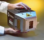
Figure 2 Diode laser systems are very compact when compared to other laser types offering similar output power.

The diode laser is a small semiconductor device that uses electrical current as its energy source. Typically, higher-power diode lasers output in the near infrared, at a slightly shorter wavelength than fiber or solid-state lasers. A typical diode laser emitter might produce at most a few watts of output power. However, it is possible to fabricate numerous emitters on a single, monolithic substrate or bar with a total output as high as 100 W. These bars can, in turn, be combined in horizontal and vertical stacks to produce high-power direct diode laser systems with total output power in the multikilowatt range.
Because of the inherent optical characteristics of diode lasers, their light output spreads out rapidly once it exits the device. As a result, the light from a diode laser system cannot be focused into a small spot, precluding keyhole welding. However, it is possible to collect the output from the individual diode emitters into an optical fiber with output that then delivers the power density necessary for conduction welding.
Diode lasers offer several distinct advantages as a welding source. For example, the process of converting electrical energy into light is many times more efficient in a diode laser because fewer steps are involved in generating the laser light. There is no excitation of a gas or need to drive a pump light source, for example. The entire electricity-to-light conversion takes place directly within a semiconductor chip.
Also, because the diode lasers themselves are monolithic, miniature devices, diode laser systemstake up little room.While the semiconductor bars must be mounted on heat sinks and require external optics, the system does not have as many individual bulk components, such as laser crystals, end mirrors, and pumping devices, as other laser types do.

Welding With Diode Lasers

Diode lasers are best-used for conduction mode welding of thin metals. Because of their small size (see Figure 2), diode laser systems can be mounted directly on robot arms and moved relatively quickly. Alternatively, the ability to deliver the output through long lengths—as much as 100 feet—of optical fiber allows a high level of flexibility in terms of where the laser system is located. It also enables beam delivery into tight or hard-to-access spaces.
Typical applications would include under-hood welding of components in automobile manufacturing and welding of heat-sensitive medical devices, such as pacemakers.
More important, diode lasers can be used with the same materials and alloys that are currently processed with conduction welding. Typical examples are medium- and high-carbon steels, which tend to form an undesirable martensitic fusion zone when subjected to the high temperatures and fast temperature cycling associated with keyhole welding.
The galvanized, or zinc-coated, steels commonly used in automotive applications also can be welded with diode lasers. Again, these are problematic with keyhole welding because the zinc melts rapidly, whereas the lower temperature of conduction welding results in a fusion zone that has a uniform dilution of zinc and steel with no porosity.
Diode lasers are also suitable for welding stainless steel. Typical examples are medical devices, reactors, and aerospace components. Again, this is because the lower process temperature doesn't cause removal of more volatile alloying elements from the fusion zone. Additionally, stainless steels are generally increasingly reflective at longer wavelengths, so the shorter wavelength of the diode laser results in incrementally better light absorption and, thus, higher efficiency.
The higher absorption of shorter wavelength light is even more pronounced in aluminum, which has a significant dip in its reflectivity in the near infrared. Aluminum alloys containing volatile alloying materials (such as magnesium), which are difficult to keyhole-weld, can be successfully conduction-welded with diode lasers.

Wilmer J Sánchez
V-19358601
seccion 1
Fuente: http://www.thefabricator.com/article/laserwelding/welding-with-diode-lasers